Reference Files and XRef Paths
by Mark Stefanchuk, CADmanage.com
 I was looking through some old emails recently and found this questions from Adrian. “How do I get the reference file path of a reference file?”
Why would you need the path? Good question. You might want to audit projects to make sure users are using standard naming conventions. You may need to include reference file names and paths in the border for cross referencing. Or, maybe, as is the case with MicroStation you want to know if the file is located in the project path or if it’s coming from another folder – another project or a common files folder like you might have for standard borders.
So, how do we do it? Well, you could open the reference dialog and hover your mouse over the file name until the pop-up window shows you the file specification, or you can write a small app.
In MicroStation we get the reference file path and file name using the designfile object with fullname. In this example, I’m just sending the name to the immediate window.
Sub reftest()
    Dim att As Attachment
    For Each att In ActiveModelReference.Attachments
        Debug.Print att.DesignFile.FullName
    Next
End Sub
AutoCAD looks a little different, because we have to search the list of blocks in the file and filter out the ones that are XREFS.
Sub xreftest()
    Dim oBlk As AcadBlock
    For Each oBlk In ThisDrawing.Blocks
        If oBlk.IsXRef Then
            Debug.Print oBlk.Path
        End If
    Next
End Sub
Printing to the immediate window is a quick and easy solution for you, but if you want your users to be able to cut and paste give them a list box or dump the results to at text file.
A listbox approach might look like this.
And the code for this is essentially the same, except you put the for each into the userform_initialize event and add items to the listbox instead of printing it to the immediate window.
 Load frmRefList
 frmRefList.Show
 frmRefList.lstXRefs.Clear
 Dim att As Attachment
 For Each att In ActiveModelReference.Attachments
    frmRefList.lstXRefs.AddItem att.DesignFile.FullName
 Next
Finally, if you want your users to be able to copy the list to the clipboard then you will have to provide a copy button because CTRL-C does not work on the list contents. This example shows you how to use a DataObject to copy the list. Put the code into a button click event and you’ll be good to go.
 Dim s As String, i As Integer, oData As DataObject
 For i = 0 To Me.lstXRefs.ListCount - 1
    If Len(Trim(Me.lstXRefs.List(i))) > 0 Then
        s = s + Trim(Me.lstXRefs.List(i)) + vbCrLf
    End If
 Next i
 Set oData = New DataObject
 oData.Clear
 oData.SetText Trim(s)
 oData.PutInClipboard
Code download is available on our CADgurus page.
About Mark Stefanchuk: Mark is a VP and senior consultant with CAD Management Resources, Inc. He divides his time between developing innovative custom software solutions and helping clients navigate complex design automation environments. If you would like to find out how he can assist you with your design technology he can be reached by contacting us at info@cadmanage.com.
Mind Bending
by Mark Stefanchuk, CADmanage.com
Brain controlled CAD – i.e. headset, no mouse? Thoughts? Not the first time I heard about this type of research, but interesting that it’s come up in the context of hacking.
Tech Crunch – “Brain Hacking: Scientists Extract Personal Secrets With Commercial Hardware”.
CNET – “Scientists start hacking minds with cheap EEG gear.”
“I can see clearly now…..”
by Seth Cohen, CADmanage.com
The other day, a user called me about visualizing her project, and she was trying to get rid of some “lines” that were not making her design look nice. This was in Civil 3D, but I thought this would make a great tip.
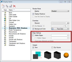
In MicroStation, the way you make the display shade is to use something called Display Styles. They are quickly accessible in the View ToolBox in any view window.
So the problem the user was having was that the Edge Settings was set to have Visible Edges toggled on. If you want to edit a display style, simply open the Display Style dialog box. To turn off the Visible Edges, simply toggle it off…….done.
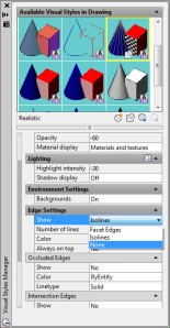
In AutoCAD, the way you make the display shade is to use something called Visual Styles. They are quickly accessible in the Visual Styles Control in any viewport.
So, in AutoCAD, the problem is Edge Settings was set to have the Show category set to Isolines. If you want to edit a visual style, simply open the Visual Styles Manager palette. To turn off the edges, simply set the Show drop-down to None…….done.
And now, a pretty picture of a rendered intersection. Can you guess which “CAD” this was rendered in? Feel free to comment and be the first to guess.
“Now you know, and knowing is half the battle.” …………G.I. Joe
Relocating the CadPilot Menu
by Lorrie Mattor, CADmanage.com
Don’t like the location of your CadPilot Menu?
Simply click and drag the Toolbar Anchor to a new location on your screen.
You like the new location and would like to keep it in the same place next time you load your CAD application? No problem, right click on the Toolbar Anchor to display the Context menu, and then select “Save Settings”.
Stay tuned for more blogs on how to incorporate other user settings in CadPilot.
Lorrie is a Technical Consultant for CADmanage.com specializing in CadPilot integration, system’s analysis, technical writing and data manipulation.

