Match Icon Check Boxes
Many years ago I created a MicroStation basic macro that would check the boxes of the match element command. At the time, MicroStation J did not save these settings, so every time you used the command you would have to check the boxes for the element attributes you wanted to change. In MicroStation V8i these settings are saved, so you only have to check the boxes one time. The basic macro (before VBA) was really simple and you could record it using the record macro dialog. VBA of course is just as easy – as we will see in a moment.
Do we still need a macro like this one? If you want all options on, or all off then there may still be room in your toolbox for this macro. It’s easy enough to record the action of checking these boxes (and unchecking the boxes). You can then add these new commands to your MicroStation menus. I like the idea of adding a couple of extra commands in my tasks menu, but adding new icons to the toolbox or pull down menu can work too.
To record the macro, open the VBA Project Manager dialog – Utilities | Macro | Project Manager.

The project manager dialog will open.

Before we record the check boxes we need to start the Match command. You can select the command from the Task menu, or type the keyin “match icon”.
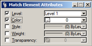
The settings dialog changes to show the Match Element Attribute controls.

To record, highlight the Default VBA and then click the red button in the Project Manager dialog. Check the boxes.

Now, click the stop button (white square) in the Project Manager dialog.

Open the Visual Basic Editor (icon that looks like a dialog box – to the right of the triangle).

The visual basic editor will contain the macro you just recorded. It will look similar to the following.

You can remove all of the Dim statements because these are not used. Remove the second last line too, CommandStatement.StartDefaultCommand. This command will stop the match command and select your default command (usually smart selector). Finally, remove all of the extra lines. The finished macro will look like this.

Repeat these steps but uncheck the boxes. Or, copy and paste Macro1 (change the new sub name to Macro2). Replace the value -1 with 0. This new macro will uncheck all of the boxes.

If you want a different name for a macro, just change the sub name. Instead of Macro1() you could replace that with MatchChkAll() and for Macro2() maybe this could be MatchChkNone().
To run the vba you can use the keyin, vba run Macro1. But, we also want to make sure tha the Match Element Attributes command has been started. So, use the following keyin,
match icon;vba run Macro1
Run this keyin from the keyin browser, add an icon to the Change Attributes toolbox and maybe create a new task. With just a little bit of effort you can optimize your workflows and create a more productive CAD environment.
About Mark Stefanchuk: Mark is a VP and senior consultant with CAD Management Resources, Inc. He divides his time between developing innovative custom software solutions and helping clients navigate complex design automation environments. If you would like to find out how he can assist you with your design technology he can be reached directly at mstefanchuk@cadmanage.com.

Transparent Dialogs
by Mark Stefanchuk, cadmanage.com
I was playing around with MicroStation preferences the other day and something was bugging me. Turning on/off dialog transparency was clumsy. I know it’s a user preference and that it’s normally on or normally off, but opening the preferences dialog, finding the transparency preference seemed to be more cumbersome than it should be. It was definitely not quick. In this case I just want to switch on/off the dialog transparency without having to go through the steps of opening checking and clicking ok – just to turn transparency on. Call me lazy.
So, to shorten the steps, I used the VBA macro recorder to capture the actions needed to turn on transparency.
To record the macro, open the VBA Project Manager dialog – Utilities | Macro | Project Manager. The project manager dialog will open. Select the Default project in the VBA Project Manager. Click the red circle to start recording.

Go to Workspace | Preferences | Look and Feel. Check the box, “All modeless dialogs use the same transparency”.

Click OK. Click Stop in the VBA Project Manager (the square white button).

I then cleaned up (deleted) all of the extra lines of code that the recorder adds. That is, the lines we don’t need.
This records the steps in your VBA. It creates a new Macro and a Macro Handler (to control the dialog box). The recording process adds a lot of extra code that we don’t need. You can remove the extra code. Your code will look similar to the following when you are done.
Sub Macro1() 'turn on dialog transparency
  Dim modalHandler As New Macro1ModalHandler
  AddModalDialogEventsHandler modalHandler
  CadInputQueue.SendCommand "MDL SILENTLOAD USERPREF"
  RemoveModalDialogEventsHandler modalHandler
End Sub
And the handler will look similar to the following.
Implements IModalDialogEvents
Private Sub IModalDialogEvents_OnDialogClosed _
  (ByVal DialogBoxName As String, _
  ByVal DialogResult As MsdDialogBoxResult)
End Sub
Private Sub IModalDialogEvents_OnDialogOpened _
(ByVal DialogBoxName As String, _
DialogResult As MsdDialogBoxResult)
  If DialogBoxName = "Preferences [untitled]" Then
    '   Set a variable associated with a dialog box
    SetCExpressionValue "savePrefs.addFlags.dialogsUseSameTranparency", 1, "USERPREF"
    '   Remove the following line to let the user close the dialog box.
    DialogResult = msdDialogBoxResultOK
  End If  ' Preferences [untitled]
End Sub
The Macro is saved in Module1 and the handler is saved in the Class Module folder of the VBA. The macro opens the preferences dialog. It also starts and stops the event handler. The handler does the work. It turns on the transparency. All of this is built for you when you record the macro. All you have to do is remove the code that you don’t need.
Next, we want a command to turn off the transparency. Just copy Macro1 and rename it as Macro2. Change Macro1ModalHandler to Macro2ModalHandler.
Sub Macro2() 'turn on dialog transparency
  Dim modalHandler As New Macro2ModalHandler
  AddModalDialogEventsHandler modalHandler
  CadInputQueue.SendCommand "MDL SILENTLOAD USERPREF"
  RemoveModalDialogEventsHandler modalHandler
End Sub
Now, create a new class module called Macro2ModalHandler. Copy the contents of Macro1ModalHandler to this new class module. Finally, in the line that starts with SetCExpressionValue, change the 1 to a 0 (i.e. on to off). Like this.
Private Sub IModalDialogEvents_OnDialogOpened _
(ByVal DialogBoxName As String, _
DialogResult As MsdDialogBoxResult)
  If DialogBoxName = "Preferences [untitled]" Then
    '   Set a variable associated with a dialog box
    SetCExpressionValue "savePrefs.addFlags.dialogsUseSameTranparency", 0, "USERPREF"
    '   Remove the following line to let the user close the dialog box.
    DialogResult = msdDialogBoxResultOK
  End If  ' Preferences [untitled]
End Sub
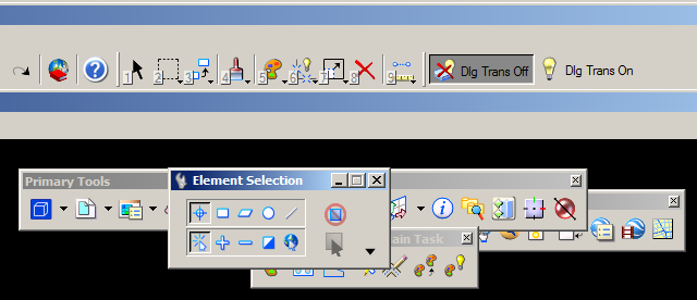
The last thing we want to do is add these commands to the UI so that we have and easy way to run the commands.To do this I added a new dgnlib to my workspace. I’m using the default untitled workspace, so I added the dgnlib to $(MS)\Workspace\projects\untitled\DGNLIB\. While in the dgnlib, open the Customize dialog box – Workspace | Customize. Add a new toolbox and two new tools. Change the names as shown in the image below.

On the first tool change the Key-in to vba run macro1. This will run the macro that turns off dialog transparency. On the second tool change the Key-in to “vba run macro2”. I’ve also changed the icon. The default tool icon is the wrench. You can select any icon you want. I just took a couple of icons from ustation.rsc (tools I don’t use very often).
Now, right click on the new toolbox name and select “Open Tool Box”.This is what mine looks like.

You can dock this on your MicroStation window. I dock mine at the top so that I can quickly access these buttons. So, now I can control dialog transparency without multiple clicks.

About Mark Stefanchuk: Mark is a VP and senior consultant with CAD Management Resources, Inc. He divides his time between developing innovative custom software solutions and helping clients navigate complex design automation environments. If you would like to find out how he can assist you with your design technology he can be reached directly at mstefanchuk@cadmanage.com.

VBA Custom Configs
by Mark Stefanchuk, cadmanage.com
I’m not really a big fan of increasing the number of MicroStation config variables. Where possible, try to use built in variables. For example, you can use CreateCellElement3
with just the name of the cell as long as the cell library is defined in MS_CELLLIST. You might have something that looks like this in your VB code.
oCell = MainForm.oMSApp.CreateCellElement3(MainForm.uc_o.txtCameraName.Text, Point, True)
This is from a VB.Net example, that’s why the MicroStation Application object is included.
Here’s how I might define MS_CELLLIST for use with photogeoDGN.
CADMANAGE = C:/ProgramData/Cadmanage/PhotogeoDGN/Contents/
MS_ADDINPATH < $(CADMANAGE)Windows/8.11/
MS_CELLLIST < $(CADMANAGE)Resources/*.cel
Sometimes however, it is necessary to identify a special folder or some other resource in your custom program. For example, your program might include a catalog file that provides some engineering data that your program will associate with a cell. You could decide to put this in a resources folder that is always in the install directory. But, a better solution might be to let the end user decide where she wants to save the resource. In this case the resource or file is one that MicroStation doesn’t know anything about, but your program has to be able to find. To fix that we could define the following,
CMRI_CATALOG = $(CADMANAGE)Resources/testcatalog.xml
Put the variable in one of MicroStation’s configuration files, like your UCF. Now, to access the variable from your custom VBA program you need to use ConfigurationVariableValue. Here’s how to do that in VBA.
Sub testConfig()
Debug.Print ActiveWorkspace.ConfigurationVariableValue("CMRI_CATALOG")
End Sub
The example will print the value of the configuration variable in the VBA IDE’s immediate window.
C:\ProgramData\Cadmanage\PhotogeoDGN\Contents\Resources\testcatalog.xml
Use this expansion to open the file, or in this case define your XML document object.

As long as the variable name is different than any other MicroStation config variable, you can use it, but I would recommend including a prefix. In the previous example, I used CMRI (for CAD Management Resources, Inc). This just helps to avoid variable conflicts.
About Mark Stefanchuk: Mark is a VP and senior consultant with CAD Management Resources, Inc. He divides his time between developing innovative custom software solutions and helping clients navigate complex design automation environments. If you would like to find out how he can assist you with your design technology he can be reached directly at mstefanchuk@cadmanage.com.
Spring FLUG!


FLUG offers you the opportunity to make connections with industry peers, exhibitors, and even your own colleagues from other offices to solve a problem you recently encountered?
Engage in hands-on, face-to-face instruction with Industry experts who have faced similar challenges to yours.
- Explore the many new product capabilities you aren’t using yet to determine how you can take advantage of them
- Glean best practices and insider tips and tricks to create new efficiencies in your workflows
- Collaborate with developers to extend the use of your software
For over 25 years, FLUG one of the countries longest running and most successful Users’ Conference and Training Events, offers you the tools to best leverage your software to better meet your strategic objectives, make the most of your resources, and stay ahead of your competition.
Check out our Agenda:
Visit our website, www.flugsite.com. Under the Main Menu portion of the webpage you will find a link to for the current Spring Agenda. A few highlights include….
- Tips and Tricks in MicroStation V8i
- DWG Interoperability with MicroStation V8i
- Point Clouds
- AECOsim Building Designer
- Bentley Navigator
- Corridor Modeling
- Autodesk Revit Architecture
- Civil 3D Plans Production
- GEOPAK Terrain
How do I register to attend FLUG?
That is easy, visit our website, www.flugsite.com. Under the Main Menu portion of the webpage you will find a link to both the current Spring Agenda and to Registration. Click the Registration link and follow the guided registration process.
Hotel Information:
Radisson Resort at the Port
8701 Astronaut Blvd.
Cape Canaveral, FL 32920 Phone: (321) 784-0000 Visit us at http://www.radisson.com/capecanaveralfl The Radisson is using a new online registration system to reserve your discount FLUG rooms. For the FLUG Government Rate (ID required at check in) please use the following link, http://www.radisson.com/fluggovernment. For the FLUG Non Government Rate please use the following link, http://www.radisson.com/flugnongovernment.
Managing Usability
by Mark Stefanchuk, CADmanage.com
[Update: Be sure to check out Kim’s comment – a great alternative using the F1 key and choose none. Thanks Kim!]
I’ve been debating whether or not to share this with my MicroStation peeps. I hesitate because I don’t like to admit that sometimes I don’t adjust to change as quickly as I should, but also because this example has some conflict with features in MicroStation V8i that we wouldn’t introduce normally, especially if we don’t have to. What am I talking about?
Earlier this year I was working with a client helping them upgrade from MicroStation 2004 to V8i SS2. Not as big of a jump from V7 to V8, but big enough. Things were missing and commands didn’t work the same way. Years ago we could rely on commands that were in the previous version to work the same way in the new version. Today, it’s not that way. And seriously, there are good reasons for change, like productivity gains. I’m all for that. In this case however, it was clear that the user base missed some of the key operations that made MicroStation, well MicroStation and not AutoCAD.
For example, in older versions of MicroStation when you were done with a selection created using power selector you would use the right mouse button to deselect (reset). In V8i you just use the right mouse button (a datapoint in the view). That’s seems pretty easy. But if you have been drafting for years using the same workflow not being able to use something so simple as the reset button to deselect a selection set can be really frustrating.
Now, I was the consultant and I really wanted my client to be happy so I fixed it. I built an MDL application that would watch for reset. When the user clicks reset any active selection set would be removed. The command is very primitive, but I thought I would share in case you might have a similar issue. There’s not much to it – comments below.
#include    <mdl.h>
#include    <tcb.h>
#include    <dlogitem.h>
#include    <dlogids.h>
#include    <rscdefs.h>
#include    <mdlerrs.h>
#include    <userfnc.h>
#include    <global.h>
#include    <mselems.h>
#include    <accudraw.h>
#include    <cexpr.h>
#include    <math.h>
#include    <string.h>

#include    "ps_resetcmd.h"
#include    "ps_reset.h"
#include    "fdf.fdf"

int goFlag; // a flag to watch for active commands that might conflict
// the event watcher
Private int monitorQueue ( Inputq_element *queueElementP )
{
    char sCmd[256];
    sprintf(sCmd, "%S", mdlState_getCurrentCommandName());

    // Element Selection Active
    if (strcmp(sCmd, "Element Selection") == 0)
    {
        goFlag = 0;
    }

    // a quick a dirty way to watch for active command - be careful with upgrades because this might not be
    // supported in the future. - not very elegant but it works - I'm a little bull headed that way.
    if ((strcmp(sCmd, "Dimension Element") == 0) || (strcmp(sCmd, "Dimension Linear Size") == 0)
        ||   (strcmp(sCmd, "Dimension Angle Size") == 0) || (strcmp(sCmd, "Dimension Ordinates") == 0)
        ||   (strcmp(sCmd, "Change Dimension") == 0) ||   (strcmp(sCmd, "Drop Dimension Element") == 0)
        ||   (strcmp(sCmd, "Dimension Size Perpendicular to Points") == 0) ||   (strcmp(sCmd, "Dimension Diameter") == 0)
        ||   (strcmp(sCmd, "Label Point Coordinate") == 0) || (strcmp(sCmd, "Dimension Symmetric") == 0)
        ||   (strcmp(sCmd, "Dimension Half") == 0) || (strcmp(sCmd, "Dimension Chamfer Angle") == 0)
        ||   (strcmp(sCmd, "Dimension Diameter Perpendicular") == 0) || (strcmp(sCmd, "Dimension Radius (Extended Leader)") == 0)
        ||   (strcmp(sCmd, "Place Center Mark") == 0) || (strcmp(sCmd, "Dimension Radius") == 0)
        ||   (strcmp(sCmd, "Dimension Arc Distance") == 0))
    {
        goFlag = 1; // the active command is a dim command so dont deselect on reset
    }
    else
    {
       goFlag = 0; // ok to reset - conflict mitigated
    }

    // user clicked reset and conflict minimized so go for it
    if (queueElementP->hdr.cmdtype == RESET)
    {
        if (goFlag == 0)
            mdlInput_sendKeyin ("powerselector deselect", 0, 0, NULL);
    }
    return INPUT_ACCEPT;
}

// command entry
int main ()
{
    RscFileHandle   rfHandle;
    goFlag = 0;

    mdlResource_openFile (&rfHandle, NULL, FALSE);

    if (mdlParse_loadCommandTable (NULL) == NULL)
        mdlOutput_rscPrintf (MSG_ERROR, NULL, 0, 4);

    mdlInput_setMonitorFunction (MONITOR_ALL, monitorQueue);
    return  SUCCESS;
}
The conflict was created by sending a command, i.e. powerselector deselect, when commands that you didn’t want to terminate using reset were active – like dimension commands. The easiest way to work around this was to set a flag. If one of the dimension commands is active then don’t deselect on reset. The code and compiled ps_reset.ma is on cadmanage.com/cadgurus. Put the ma in your mdlapps folder so it will load when MicroStation is loaded. You can also use the keyin mdl load ps_reset to load this app.

About Mark Stefanchuk: Mark is a VP and senior consultant with CAD Management Resources, Inc. He divides his time between developing innovative custom software solutions and helping clients navigate complex design automation environments. If you would like to find out how he can assist you with your design technology he can be reached by contacting us at info@cadmanage.com.
CadPilot – Menu Item Help Files
by Lorrie Mattor, CADmanage.com
Create help files for any command within CadPilot menus!
Toolbar menus are loaded from menu xml files as specified by your current configuration and appear in CadPilot toolbars.
If a Help File command is associated with the menu icon then the cursor will appear as a hand while floating over the menu icon. When the icon is selected the Help file will open. To execute the menu command simply slide your cursor over the command text until the cursor displays as an Arrow.

There may be times when a Help file is not associated with the Menu icon, in these cases the cursor will be displayed as an Arrow and the Menu command will be issued (even when selecting the icon).

If your command does not have a help file associated with it and you feel it would be helpful, contact your CadPilot Administrator (Cad Manager) to add it to the CadPilot menu.
Lorrie is a Technical Consultant for CADmanage.com specializing in CadPilot integration, system’s analysis, technical writing and data manipulation.

Reference Files and XRef Paths
by Mark Stefanchuk, CADmanage.com
 I was looking through some old emails recently and found this questions from Adrian. “How do I get the reference file path of a reference file?”
Why would you need the path? Good question. You might want to audit projects to make sure users are using standard naming conventions. You may need to include reference file names and paths in the border for cross referencing. Or, maybe, as is the case with MicroStation you want to know if the file is located in the project path or if it’s coming from another folder – another project or a common files folder like you might have for standard borders.
So, how do we do it? Well, you could open the reference dialog and hover your mouse over the file name until the pop-up window shows you the file specification, or you can write a small app.
In MicroStation we get the reference file path and file name using the designfile object with fullname. In this example, I’m just sending the name to the immediate window.
Sub reftest()
    Dim att As Attachment
    For Each att In ActiveModelReference.Attachments
        Debug.Print att.DesignFile.FullName
    Next
End Sub
AutoCAD looks a little different, because we have to search the list of blocks in the file and filter out the ones that are XREFS.
Sub xreftest()
    Dim oBlk As AcadBlock
    For Each oBlk In ThisDrawing.Blocks
        If oBlk.IsXRef Then
            Debug.Print oBlk.Path
        End If
    Next
End Sub
Printing to the immediate window is a quick and easy solution for you, but if you want your users to be able to cut and paste give them a list box or dump the results to at text file.
A listbox approach might look like this.

And the code for this is essentially the same, except you put the for each into the userform_initialize event and add items to the listbox instead of printing it to the immediate window.
 Load frmRefList
 frmRefList.Show
 frmRefList.lstXRefs.Clear
 Dim att As Attachment
 For Each att In ActiveModelReference.Attachments
    frmRefList.lstXRefs.AddItem att.DesignFile.FullName
 Next
Finally, if you want your users to be able to copy the list to the clipboard then you will have to provide a copy button because CTRL-C does not work on the list contents. This example shows you how to use a DataObject to copy the list. Put the code into a button click event and you’ll be good to go.
 Dim s As String, i As Integer, oData As DataObject
 For i = 0 To Me.lstXRefs.ListCount - 1
    If Len(Trim(Me.lstXRefs.List(i))) > 0 Then
        s = s + Trim(Me.lstXRefs.List(i)) + vbCrLf
    End If
 Next i
 Set oData = New DataObject
 oData.Clear
 oData.SetText Trim(s)
 oData.PutInClipboard
Code download is available on our CADgurus page.
About Mark Stefanchuk: Mark is a VP and senior consultant with CAD Management Resources, Inc. He divides his time between developing innovative custom software solutions and helping clients navigate complex design automation environments. If you would like to find out how he can assist you with your design technology he can be reached by contacting us at info@cadmanage.com.
“I can see clearly now…..”
by Seth Cohen, CADmanage.com
The other day, a user called me about visualizing her project, and she was trying to get rid of some “lines” that were not making her design look nice. This was in Civil 3D, but I thought this would make a great tip.
In MicroStation, the way you make the display shade is to use something called Display Styles. They are quickly accessible in the View ToolBox in any view window.

Display Styles Drop-Down
So the problem the user was having was that the Edge Settings was set to have Visible Edges toggled on. If you want to edit a display style, simply open the Display Style dialog box. To turn off the Visible Edges, simply toggle it off…….done.

Display Style dialog box
In AutoCAD, the way you make the display shade is to use something called Visual Styles. They are quickly accessible in the Visual Styles Control in any viewport.

Visual Styles Control
So, in AutoCAD, the problem is Edge Settings was set to have the Show category set to Isolines. If you want to edit a visual style, simply open the Visual Styles Manager palette. To turn off the edges, simply set the Show drop-down to None…….done.

Visual Styles Manager Palette
And now, a pretty picture of a rendered intersection. Can you guess which “CAD” this was rendered in? Feel free to comment and be the first to guess.

Pretty Intersection
“Now you know, and knowing is half the battle.” …………G.I. Joe

Using TabLists in CadPilot
by Lorrie Mattor, CADmanage.com
We’re introducing a new blog post this month for our CADpilot users. I will be adding at least one new tip per month and if there is a topic you would like me cover send me an email at info@cadmanage.com or fill out our contact us form located on our main cadmanage.com page.
Do you prefer to work with lists of information? Do you have many levels or cells/blocks to chose from and need a quick and easy way to organize…with non-cryptic descriptions? TabLists are the answer to display and execute commands in a list format. Ask your CadPilot administrator to setup a TabList for you.
The following is an example of a TabList and instructions on navigating and using TabLists. 
Use your mouse to select the applicable category tab, then click on the desired name (level name in this example) to execute the command.
ADA compliant commands also available:
The arrows keys may also be used to navigate the tabs and commands within the list(s).
Left arrow key navigates between multiple tabs
Right arrow key navigates between multiple tabs
Down arrow key navigates down through the current list.
Up arrow key navigates up through the current list.
Additional key commands available:
<PageUp> key navigates up through the list a page at a time.
<PageDn> key navigates down through the list a page at a time.
<Enter> key activates the currently selected item.

Lorrie is a Technical Consultant for CADmanage.com specializing in CadPilot integration, system’s analysis, technical writing and data manipulation.
Zoom, zoom zoom
by Seth Cohen, CADmanage.com
Ok, so we’re going to get down to the basics here, what is the best way to zoom in AutoCAD and MicroStation? Well, as it turns out, they both work exactly the same (for the most part). Basically, you use the middle mouse button by itself, or with some kind of keyboard combination.
Zoom in
Simple one here, wheel towards your computer to zoom in, and wheel towards you to zoom out. Associated variables or settings:
AutoCAD
ZOOMFACTOR variable
MicroStation
In the Preferences dialog box > Mouse Wheel Category
Pan
Even simpler, hold the middle mouse button. Associated variables or settings:
AutoCAD
MBUTTONPAN will toggle whether the middle mouse button will support the action defined in the CUI file or pan.
MicroStation
You can also pan by holding down the SHIFT+Left Mouse Button, and moving your mouse.
Zoom Extents
Double-click the middle mouse button. Associated variables or settings:
AutoCAD
None
MicroStation
None
3D Orbit
Hold down the SHIFT+Middle Mouse Button, and move your mouse. Associated variables or settings:
AutoCAD
None
MicroStation
If you snap (left+right mouse buttons) to an element, you will center the 3D orbit point.
And that’s it!
“Now you know, and knowing is half the battle.” …………G.I. Joe
