Spring FLUG!


FLUG offers you the opportunity to make connections with industry peers, exhibitors, and even your own colleagues from other offices to solve a problem you recently encountered?
Engage in hands-on, face-to-face instruction with Industry experts who have faced similar challenges to yours.
- Explore the many new product capabilities you aren’t using yet to determine how you can take advantage of them
- Glean best practices and insider tips and tricks to create new efficiencies in your workflows
- Collaborate with developers to extend the use of your software
For over 25 years, FLUG one of the countries longest running and most successful Users’ Conference and Training Events, offers you the tools to best leverage your software to better meet your strategic objectives, make the most of your resources, and stay ahead of your competition.
Check out our Agenda:
Visit our website, www.flugsite.com. Under the Main Menu portion of the webpage you will find a link to for the current Spring Agenda. A few highlights include….
- Tips and Tricks in MicroStation V8i
- DWG Interoperability with MicroStation V8i
- Point Clouds
- AECOsim Building Designer
- Bentley Navigator
- Corridor Modeling
- Autodesk Revit Architecture
- Civil 3D Plans Production
- GEOPAK Terrain
How do I register to attend FLUG?
That is easy, visit our website, www.flugsite.com. Under the Main Menu portion of the webpage you will find a link to both the current Spring Agenda and to Registration. Click the Registration link and follow the guided registration process.
Hotel Information:
Radisson Resort at the Port
8701 Astronaut Blvd.
Cape Canaveral, FL 32920 Phone: (321) 784-0000 Visit us at http://www.radisson.com/capecanaveralfl The Radisson is using a new online registration system to reserve your discount FLUG rooms. For the FLUG Government Rate (ID required at check in) please use the following link, http://www.radisson.com/fluggovernment. For the FLUG Non Government Rate please use the following link, http://www.radisson.com/flugnongovernment.
Civil 3D Offset Alignments
by Seth Cohen, CADmanage.com
Civil 3D offest alignments are a great way to add transitions into your design that subassemblies can then target.
I have had many users get a little confused as to how to enter the stationing. When you first start using offset alignments, you add the full offset width stations, and not the station to station limits of the transition area. A very easy way to add the transition after you add the offset distance, is to simply select the Transition Grips. To make the transition grips appear, select the offset alignment, and click the large circular grip.

Click to get Transition Grips
Next, select one of the Transition Segment Length grips (make sure you have Dynamic Input turned on), and type the station where the transition should begin/end, depending on which grip you select.

Transition Segment Length Grip
It’s that easy.
“Now you know, and knowing is half the battle.” …………G.I. Joe

About Seth Cohen: Seth is Vice President of Training at CAD Management Resources Inc., specializing in civil engineering and CAD applications including Civil 3D®, Map 3D, AutoCAD®, MicroStation®, and InRoads®. He has conducted many classes for CAD professionals ranging from commercial to government organizations. If you would like to find out how he can assist you with your training needs he can be reached by contacting us at info@cadmanage.com.
PhotogeoDWG on Windows XP
by Mark Stefanchuk, CADmanage.com
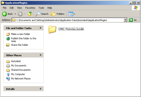
I just finished up some testing running PhotogeoDWG in AutoCAD 2013 on Windows XP (SP3) and the results are good. The Autodesk Exchange Apps Store installer copies the Photogeo bundle into %appdata%, as it does in Windows 7. But in XP, the AppData location is in the Documents and Settings Application Data folder of the current user, and not in the user’s roaming folder.
Autoloader worked great in AutoCAD 2013 and I was able to run all PhotogeoDWG features as expected. So, if you’re holding off on running tools available via Exchange apps because your expecting conflicts with Windows, there’s actually no need to wait.

About Mark Stefanchuk: Mark is a VP and senior consultant with CAD Management Resources, Inc. He divides his time between developing innovative custom software solutions and helping clients navigate complex design automation environments. If you would like to find out how he can assist you with your design technology he can be reached by contacting us at info@cadmanage.com.
PhotoGeoDWG on Exchange Apps!
by Mark Stefanchuk, CADmanage.com

Just a quick note to announce that PhotoGeoDWG is now available on the Autodesk Exchange Apps Store. Leave a comment, tell us how to make it better. PhotoGeo will run in AutoCAD 2012/2013 and Civil3D 2012/2013. And, did I mention it’s free? Our CADmanage.com help page has a link to the PhotoGeoDWGhelp.pdf (right click on the link to download the file).
Zoom, zoom zoom
by Seth Cohen, CADmanage.com
Ok, so we’re going to get down to the basics here, what is the best way to zoom in AutoCAD and MicroStation? Well, as it turns out, they both work exactly the same (for the most part). Basically, you use the middle mouse button by itself, or with some kind of keyboard combination.
Zoom in
Simple one here, wheel towards your computer to zoom in, and wheel towards you to zoom out. Associated variables or settings:
AutoCAD
ZOOMFACTOR variable
MicroStation
In the Preferences dialog box > Mouse Wheel Category
Pan
Even simpler, hold the middle mouse button. Associated variables or settings:
AutoCAD
MBUTTONPAN will toggle whether the middle mouse button will support the action defined in the CUI file or pan.
MicroStation
You can also pan by holding down the SHIFT+Left Mouse Button, and moving your mouse.
Zoom Extents
Double-click the middle mouse button. Associated variables or settings:
AutoCAD
None
MicroStation
None
3D Orbit
Hold down the SHIFT+Middle Mouse Button, and move your mouse. Associated variables or settings:
AutoCAD
None
MicroStation
If you snap (left+right mouse buttons) to an element, you will center the 3D orbit point.
And that’s it!
“Now you know, and knowing is half the battle.” …………G.I. Joe
Information to Help You Better Manage Your CAD Environment
by Mark Stefanchuk, CADmanage.com
Information is the key. Without it we can’t analyze and resolve issues, or win funding for new initiatives. As a CAD Manager, one of the toughest things I had to do was present and support the business case for moving projects forward. It required formulating data in a way that each stake holder could understand. Often that was a monetary presentation other times it was technical. We need information that can help us to understand overall operations, as well as detailed data about each workstation. With information readily available we will have much better control of the CAD ecosystem and a better argument when we have to reach out to our boss for funding. Here are five things, pieces of information, that can help you manage your CAD environment.
Computer Names
Capture computer names to support automated deployments. If you have a small footprint this is easy enough to manage and you probably aren’t doing automated deployments – but can offer you insights when combined with other data. In larger environments, especially those with self service request centers knowing who has what software isn’t always that easy. Even if you have a small pool of licenses your installed base could be much larger. Automating license capture is necessary and can help you with the next deployment.
User Names
In addition to providing very granular usage stats, user names can also provide data on asset usage – shared and individual. Tracking user names per computer name can tell you how effectively you are using your hardware assets. And you may find there are opportunities to consolidate resources or in some cases pro-actively address maintenance issues for shared resources. You can extend usage monitoring to just about any asset including software. In large environments software deployment, including CAD software is often managed by a centralized IT department. In this scenario CAD Managers will quickly lose track of who has and is using critical software assets.
How can we capture username and computer name? In a small environment (say fewer than 10) you can just survey the team and catalog the data manually. In larger environments you will want to use automation to capture this data. A quick and easy way to do this is to add some code to your start up script or program. In VBA you can use the following…
   Dim sComp as String, sUser as String
   sComp = $Environ(“computername”)
   sUser = $Environ(“username”)
And a quick way to save this data is to just append it to a log file using the open and print statements. Check http:\\en.wikibooks.org\wiki\Visual_Basic\Files for details on writing text files. Of course a more sophisticated approach would be to use a SQL database or some other data system that you can query and report.
Version Audit
Going a step further in your intelligence gathering you might also consider capturing version dates on first tier software. These include your business critical applications – that is MicroStation, AutoCAD, Civil3D, and so on. Version audits can help to avert support issues. For example, incompatible plug-ins.
In both MicroStation and AutoCAD VBA this is easy – it’s just a simple call to the application object.
Application.Version
In addition to analyzing support issues, version audits can also help with funding – as is the case with Adobe applications where each version counts as a license instance. In larger environments with self service software requests I’ve seen incorrect versions deployed and version audits can help identify workstations that need to be upgraded. For those of you working for a consulting shop, it’s not unusual to be running multiple versions because in these situations we tend to upgrade as users finish one project and are just starting a new project. So in this case we can use version audits to avoid potential production losses.
In smaller environments versions and software deployments are more easily managed, but if you’re managing a reasonably sized CAD ecosystem computer names, user names, and versions can provide better feedback from your CAD environment. And there are many other things you might want to consider tracking – hardware form factors, plotter usage, and user profiles – each provides valuable information and combined they can inform upgrade schedules, refresh strategy, and software management policies. I’ll investigate these more in future posts, but for now experiment with user, computer, and versions, and let me know what else you might want to track.

About Mark Stefanchuk: Mark is a VP and senior consultant with CAD Management Resources, Inc. He divides his time between developing innovative custom software solutions and helping clients navigate complex design automation environments. If you would like to find out how he can assist you with your design technology he can be reached by contacting us at info@cadmanage.com.
Launching External Programs and CADpilot
by Mark Stefanchuk, CADmanage.com
Yesterday I was looking at launching external applications from my favorite CAD programs. Launching standard Windows office applications are generally supported, but I wanted to see if I could launch an executable developed by someone other than Microsoft. Sure enough, there are several posts out there that document how to do this, but I thought it might be helpful to see how to handle it in both MicroStation and AutoCAD. And many of our CADpilot customers have asked the same thing, specifically “how do I launch an external application using CADpilot?” So, I’ve included a couple of CADpilot examples too.
MicroStation
In MicroStation this is easy. Use the “%” symbol before the application name. For example,
%snagit32
As long as snagit32.exe is found in a PATH folder the program will launch. If it’s not in the path then you can always be explicit. For example,
%"C:\Program Files (x86)\SDJElectra\SegmentTables\Program\segmenttables.exe"
The quotes are necessary because there are spaces in the path spec.
AutoCAD
In AutoCAD it takes a little more effort, but you can do it. The START command will launch most windows programs found in PATH. If it’s not found in path you will need to use the SHELL command. For example,
SHELL "C:\Program Files (x86)\SDJElectra\SegmentTables\Program\segmenttables.exe"
These will start a command window which then executes the request.
You can also set up an alias by editing the acad.pgp file. To open this file in Civil3d go to the Manage tab on the ribbon menu and click “Edit Aliases”. This will open the file in notepad. You can find more information on how to add aliases for external programs from the knowledgebase article, Starting Windows programs from the AutoCAD command line.

The interesting thing about the alias file is that it is user specific. If you do a Save-As from notepad you will see that the acad.pgp file is located in the users AppData folder. It will move with the user’s roaming profile, but everyone could have a different acad.pgp.

That’s great. It gives your users control over their personal CAD environment. On the other hand, you will have to do some planning if you, as the CAD Manager, make changes to this file and want to deploy it to everyone on the team.
CADpilot
A somewhat biased plug – this is one of the many reasons I like CADpilot. The user can create her own aliases and you can deliver program launch commands for the whole team, or for segments of your team to a single location. Also, since CADpilot is a delivery and deployment platform you can make global changes very easily without making users exit their design session.
Ok, so for those of you already using CADpilot, launching commands is really easy. You use the “cadpilot ui run” command. In MicroStation it will look like this,
cadpilot ui run snagit32
and for AutoCAD,
(cadpilot-ui-run snagit32)
If you need to spec the whole path then use the following format.
(cadpilot-ui-run "C:/Program Files (x86)/SDJElectra/SegmentTables/Program/segmenttables.exe")
In the editor it would look like this.

On my development menu I’ve just added it as a test – like this,

It looks the same in both MicroStation and AutoCAD, there’s no DOS command shell opened when the command launches, and I only had to deploy it to one location.
I also discovered, today, that I can add my own variables to cadpilot.ui.cfg file. I added,
MYPATHVAR = C:/mydevpath/
The new commands for MicroStation and AutoCAD,

You don’t have to exit the CAD application either, just reload the menu.
If you’re not already a CADpilot user, download the demo version from cadmanage.com.
About Mark Stefanchuk: Mark is a VP and senior consultant with CAD Management Resources, Inc. He divides his time between developing innovative custom software solutions and helping clients navigate complex design automation environments. If you would like to find out how he can assist you with your design technology he can be reached by contacting us at info@cadmanage.com.
“I need to get a surface from Civil 3D for InRoads, I’ll just export a LandXML file, right?”
by Seth Cohen, CADmanage.com
So, you are asked to give a surface that you created in Civil 3D to a company that uses Bentley InRoads. You assume, because you have heard it from everyone, just export it to LandXML and all will be good. Well, that works……….sometimes. Let’s look at some reasons why this is not always %100 correct.
In the example below, my surface in Civil 3D looks perfect.

Surface in Civil 3D
However, when the surface is translated in InRoads from the LandXML file, this is what it looks like.

Surface in InRoads
So, as you can see, sometimes it is not a one-to-one translation. In this example the reason the surface did not come in properly is that in Civil 3D, the triangles were deleted and a surface boundary was not used to “bound” the surface. The solution in this example is to extract the boundary of the surface in Civil 3D, and bring it into the surface as an Outer Boundary. When the surface is translated into InRoads, the surface boundary will come in as a breakline, allowing the InRoads user to use the boundary to create an Exterior Boundary (as it’s called in InRoads).
Another issue is shown below in the following images:

TIN in Civil 3D

TIN in InRoads
As you can see, the triangles don’t match up, and the InRoads user is not going to know that the triangles are incorrect. Now sometimes this is more of an issue in each software package and the different algorithms used to triangulate the surface, and the InRoads user will have to Change Triangle Edges (Swap Edge in Civil 3D) to match the correct triangulation. However, with the correct data provided to the InRoads user, the surface can match the Civil 3D version.
So, what can you do to ensure that an accurate surface will be reproduced in InRoads? Here are some tips that will help ensure a more accurate model representation.
- Add an exterior boundary to the surface (as mentioned in the first section)
- Make sure the surface is using a style that shows triangles, and export the DWG to either a MicroStation DGN file or AutoCAD graphics. This will allow the InRoads user to see how the surface should look (triangulation-wise). Additionally, the InRoads user will have whatever 3D graphics they will need to make the surface work correctly.
- Verify that the necessary settings are defined in the LandXML Settings dialog box. This dialog box is found in the Settings tab > right-click on the drawing name > Select Edit LandXML Settings.

“Now you know, and knowing is half the battle.”…………G.I. Joe
